| Phys 198 | February 20, 1997 |
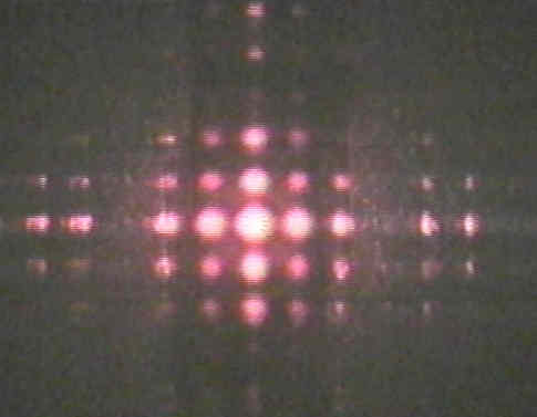
![]() [The intent here was to allow
determination of slit width b just from measurements
made from the image, given only the wavelength of the light used.
However, in fact, the problem turns out to be quite difficult to
solve, so I wish I had not assigned it as the first question in
the first lab assignment.] The procedure is to realize that the
geometry has to be determined, i.e., two of the
following three quantities must be determined: {y
displacement from central axis line, L separation
between slit and screen, qi
angle from central axis to ith fringe}. To determine
two unknowns, two linearly independent equations must be
obtained. If measurements are made of distances between two sets
of corresponding dark fringe orders on both side of central axis,
the results are not independent, because dark fringe spacings are
multiples of each other. So have to measure bright fringes, which
are not evenly spaced. Also, the measurement must be to the peak
of the bright fringe, not what appears to be the center
of the fringe. To do this, the image shown above must be
converted in ImageTool to a grayscale image, and
then a line profile taken of the horizontal axis through the
center of the pattern. When this is done, it is clear that the
peaks are noisy, so they must be smoothed by eye to pick the
location of the brightest part of the fringe. It appears that the
peaks are too noisy to allow enough accuracy to get reliable
results. However, assume that the peak can be smoothed
sufficiently to locate its peak accurately. The next step is to
compare the measured distances from midpoint of the central
bright spot to the peak of two bright fringes to the locations
where the sinc2() function has its maximum values;
these points can be taken from the included graph of sinc2(b). Since the sinc2() function
has a maximum whenever its argument agrees with one of the peak
values shown on the graph, and since bi
= (kbsinqi)/2, where qi = atan(yi/L), the
two data values can be obtained as follows. Let the two peak
values of b taken from the graph be
represented as b1 and b2, and let the corresponding
measured distances taken from the image be y1 and y2.
Then b1
= p b sin(atan(y1/L))/l and b2
= p b sin(atan(y2/L))/l are two equations in two unknowns
(b, L). They can be solved (with considerable
effort) to determine b.
[The intent here was to allow
determination of slit width b just from measurements
made from the image, given only the wavelength of the light used.
However, in fact, the problem turns out to be quite difficult to
solve, so I wish I had not assigned it as the first question in
the first lab assignment.] The procedure is to realize that the
geometry has to be determined, i.e., two of the
following three quantities must be determined: {y
displacement from central axis line, L separation
between slit and screen, qi
angle from central axis to ith fringe}. To determine
two unknowns, two linearly independent equations must be
obtained. If measurements are made of distances between two sets
of corresponding dark fringe orders on both side of central axis,
the results are not independent, because dark fringe spacings are
multiples of each other. So have to measure bright fringes, which
are not evenly spaced. Also, the measurement must be to the peak
of the bright fringe, not what appears to be the center
of the fringe. To do this, the image shown above must be
converted in ImageTool to a grayscale image, and
then a line profile taken of the horizontal axis through the
center of the pattern. When this is done, it is clear that the
peaks are noisy, so they must be smoothed by eye to pick the
location of the brightest part of the fringe. It appears that the
peaks are too noisy to allow enough accuracy to get reliable
results. However, assume that the peak can be smoothed
sufficiently to locate its peak accurately. The next step is to
compare the measured distances from midpoint of the central
bright spot to the peak of two bright fringes to the locations
where the sinc2() function has its maximum values;
these points can be taken from the included graph of sinc2(b). Since the sinc2() function
has a maximum whenever its argument agrees with one of the peak
values shown on the graph, and since bi
= (kbsinqi)/2, where qi = atan(yi/L), the
two data values can be obtained as follows. Let the two peak
values of b taken from the graph be
represented as b1 and b2, and let the corresponding
measured distances taken from the image be y1 and y2.
Then b1
= p b sin(atan(y1/L))/l and b2
= p b sin(atan(y2/L))/l are two equations in two unknowns
(b, L). They can be solved (with considerable
effort) to determine b.
![]()
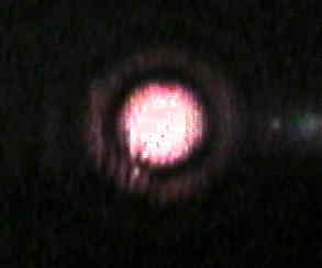
![]() Since the value
of the angle to the third bright fringe is given as q3 = 0.007718 rad, this problem
is much easier. Ignoring the sequence of questions for a moment,
the easiest measurement is to determine the slit spacing a
by using the formula a sin q3
= 3l which gives a
= 0.246 mm. The simplest way to get the slit width b is
to determine by inspection that a missing order occurs when the 8th
bright order coincides with the first diffraction order (dark).
Therefore a/b = 8/1 or b = a/8 or b
= 0.031 mm. To answer the final question concerning
corroboration, a second method of determining b must be
applied. To do this, use the given datum that q3
= 0.007718 rad = y3/L' for
the third bright fringe. This gives the value of L'
corresponding to whatever the magnification of the imaging system
is. Measure the distance y1 between
the center spot of the image and the first dark fringe. Applying b
sin (y1/L') = b y1/L'
= l gives an independent
determination of b, which can be compared to the value
obtained by using the missing order approach.
Since the value
of the angle to the third bright fringe is given as q3 = 0.007718 rad, this problem
is much easier. Ignoring the sequence of questions for a moment,
the easiest measurement is to determine the slit spacing a
by using the formula a sin q3
= 3l which gives a
= 0.246 mm. The simplest way to get the slit width b is
to determine by inspection that a missing order occurs when the 8th
bright order coincides with the first diffraction order (dark).
Therefore a/b = 8/1 or b = a/8 or b
= 0.031 mm. To answer the final question concerning
corroboration, a second method of determining b must be
applied. To do this, use the given datum that q3
= 0.007718 rad = y3/L' for
the third bright fringe. This gives the value of L'
corresponding to whatever the magnification of the imaging system
is. Measure the distance y1 between
the center spot of the image and the first dark fringe. Applying b
sin (y1/L') = b y1/L'
= l gives an independent
determination of b, which can be compared to the value
obtained by using the missing order approach.
 Diffraction
from a Square Aperture
Diffraction
from a Square Aperture This is really the same as Problem #1 and is solved the same way. Since the aperture is square, measurements can be taken either along the horizontal or the vertical axis.
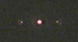
![]()
 Skipping special case that
occurs when b = 0, record the second
and third given data values when the Bessel function J1(b) = 0. Measure diameters y1 and
y2 of the first two dark fringes. Set up two equations
much like process in Problem 1.
Skipping special case that
occurs when b = 0, record the second
and third given data values when the Bessel function J1(b) = 0. Measure diameters y1 and
y2 of the first two dark fringes. Set up two equations
much like process in Problem 1.
![]()
 Given the line
density N (= 13,400 lines/inch) of the original grating, and the
distance L (= 6.3 cm) between the grating and the Lab
screen, determine the magnification of the image on the monitor
display. This is rather easy, since some of the geometry is
given. First invert the line density to get line spacing: a
= 1 inch/13,400 lines = 7.463 10-5 inch = 1.896 cm.
Use first order bright spots with l =
633 nm, so a sin q1
= l, which gives ay1/L
= l, where y1
is the original lateral displacement of the first order bright
from the central spot on the lab screen. Now use a ruler to
determine y by measuring the distancebetween the +/-
1 orders on the display being used and dividing by 2. The
magnification is then given by y/y1.
Given the line
density N (= 13,400 lines/inch) of the original grating, and the
distance L (= 6.3 cm) between the grating and the Lab
screen, determine the magnification of the image on the monitor
display. This is rather easy, since some of the geometry is
given. First invert the line density to get line spacing: a
= 1 inch/13,400 lines = 7.463 10-5 inch = 1.896 cm.
Use first order bright spots with l =
633 nm, so a sin q1
= l, which gives ay1/L
= l, where y1
is the original lateral displacement of the first order bright
from the central spot on the lab screen. Now use a ruler to
determine y by measuring the distancebetween the +/-
1 orders on the display being used and dividing by 2. The
magnification is then given by y/y1.
![]()