| Phys 198 |
January 29, 1997 |
THE POLARISCOPE

Components of a Polariscope:
- Polarizer and Analyzer If the polarizer
and analyzer are crossed, so that no light exits from the
analyzer, the setup is called dark field. Light
will only be transmitted due to effects resulting from
birefringence in the model. If the polarizer and analyzer
are aligned to pass all the light going through the
system, the setup is called light field. The
effect of the model is to then darken the image. Almost
all work is done in the dark field setup. Two types of
fringes occur in the image: isochromatics,
which identify the magnitude of the maximum shearing
stress vector by their color, and isoclinics,
which give the direction of the maximum shearing stress
vector.
- Two Quarter-Wave Plates The two quarter
wave plates are aligned in crossed mode with the fast
axis of one aligned with the slow axis of the other. The
purpose of the quarter wave plates is to convert the
incoming linearized polarized light to circularly
polarized light before the light goes through the model,
and then convert the light emerging from the model back
into linearly polarized light before it passes through
the analyzer. Actually, these plates are not necessary,
but they remove the isoclinic lines from the pattern so
as to produce a clear isochromatic pattern. They can be
removed physically, or optically by aligning their axes
with the polarizer axes.
- Loading Mechanism Some type of mechanism
is required to load the model specimen. It must be placed
between the polarizer and quarter-wave pairs.
- Light Source with Filters The light
source can either be standard white light or a
monochromatic source (usually with a wavelength matching
the tint-of- passage, which is also the design wavelength
of the quarter-wave plates). White light gives colored
fringes, isochromatics, which aid in estimating
stresses, but has the disadvantage that only a very few
colored fringes can be distinguished easily.
Monochromatic light, on the other hand, gives much
narrower fringes which can be observed up to much higher
order. In either case, the light must be expanded to the
size of the model area it is desired to study. The beam
can be either from an extended source (fluorescent or
incandescent bulbs) diffused by a ground glass, or from a
point source (arc lamp or discharge tube) with the light
beam expanded and collimated by a collimating lens. Large
collimating lenses are expensive, so much work is done
with diffuse light sources. In this case however, a telecentric
imaging system should be used to select out the light
which traveled parallel through the specimen.
- Image Detector This can be a camera film
(preferably one with high contrast), a CCD digital
camera, or the human eye. Frequently, a ground glass
plate is fixed to a camera film plane for visual
inspection and alignment, then replaced with film for
obtaining a permanent image. In recent times, there has
of course been great interest in digital images from a
CCD.
- Collimating and Field Lenses The
collimating lens is used as described above. The field
lens is used to focus the large image exiting from the
polariscope down onto an image detector.
Example:
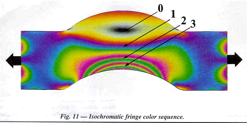
The following image is taken from the Measurements Group Wall
Chart and shows the isochromatic fringe pattern obtained when a
curved plastic (PSM-1) model of a curved bar is subjected to
tensile stress.

Last Modified on 20 April, 1997


