| Phys 198 | February 10, 1997 |

Moire is a French word for silk, which shows dark fringes when one layer of the silk slides over another layer. However, in making moire measurements, two grids of evenly spaced lines are carefully prepared and superposed. One grid is never changed and is called the master grating. The other grating, affixed to a specimen under test, is called the specimen grating and is distorted whenever the specimen distorts under loading. The grid spacing of the master grating is called the pitch p, while the varying pitch of the specimen grating is p', and the direction perpendicular to the lines of the master grating is called the principal direction.
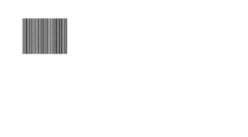
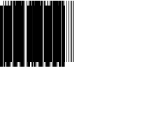
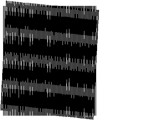
There are two methods in which moire fringes are produced. One method creates a moire when the specimen grating, originally aligned parallel to the master grating, is distorted or elongated in the principal direction. The second method produces moire fringes when the specimen grid is rotated with respect to the master grid. A basic difference between the two cases is the direction of the moire fringes. In elongation the fringes are parallel to the lines of the two grids, while for rotation the moire lines bisect the obtuse angle between the lines of the two grids. For small angles, this means that the moire fringes are essentially perpendicular to the grid lines for rotation, and parallel to the grid lines for elongation. Examine the moire in the examples given below.
![]()
Elongation of the specimen grid perpendicular to the direction
of the lines will produce a moire when beat against the master
grid. Assuming that the specimen is uniformly extended, the
grating affixed to it will have a new pitch p. If the two grids are aligned
with their lines parallel and the motion is in the principal
direction, a series of fringes, known as moire fringes, will
appear. The number of moire fringes over a specified gage length Lo
is dependent on the amount of extension undergone by the specimen
grid and is given by the relationship DL
= Np, where p is the master pitch, N is
the number of fringes appearing within the gage length Lo,,
and DL is the length
extension of the specimen from the original gage length. The
effect is purely a matter of one grid occluding part of the
other, and does not involve any diffraction or interference
theory. The key result is that one fringe is generated every time
the extension is equal to the fringe spacing p. This
allows the measurement of strain along the principal direction; i.e.,
e = DL/Lo
= d(Np)/dL = p(dN/dL). Of course, if the elongation is
uniform, the strain is constant and has the value e = pN/Lo.
![]()

Fringes also occur if two gratings are rotated with respect to each other, even if the grating pitches are the same. The angle between the lines of the specimen grating and the master grating is q, while the angle between the moire fringe lines and the master grating lines is f. What is observed in the image is f, so it is desired to find the relationship between q and f. Recall that the moire fringes bisect the obtuse angle between the master and specimen gratings. Therefore if the rotation angle is q, then the moire angle f = p/2 + q/2, or q = 2f - p.
Usually the two effects of elongation and rotation do not occur separately, and so they must be separated analytically when it is desired to determine the stress and rotation at some chosen point. Of course, when the elongation of the specimen pitch is uniform, it does not matter which point is chosen.
![]()
Last Modified on April 20, 1997