Another use of moire, quite different from uses already discussed, is in measuring out-of-plane displacements, either for the purpose of contouring surfaces, or to monitor displacements normal to the surface under study. Other methods of moire give only in-plane data, so it can be useful to obtain information about changes in the third dimension. The two most commen methods for out-of-plane measurement are shadow moire and projection moire. Neither of these methods involves the use of more than a single real grid, and depending on the method used only the shadow of a grid or a projected grid image is placed on the specimen. It should be noted that it is assumed that only out-of-plane measurements are being made and that no in-plane displacement occurs during the measurements. Combining in-plane and out-of-plane motion makes the images very difficult to interpret.
![]()
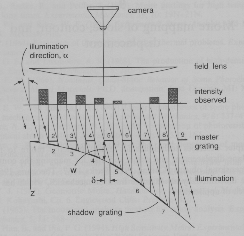
The basic idea of shadow moire is quite simple. A single master grid is used, placed close to the surface under study. A collimated beam of light illuminates the surface from an angle a with respect to the normal. The shadow of the original grid falls onto the surface and is used as the specimen grid. As the surface moves back and forth normally to the master grid, the shadow fringes coming in at an angle get wider and move further away from or closer to their original position. Thus a change in longitudinal motion has been converted to a change in lateral motion, which is what moire is good at measuring. One fringe will appear when the shadows of m lines are broadened and stretched to cover m+1 master grating lines, that is, when the lateral change of the shadow grid equals the pitch of the master grid.. If w is the change in the z distance between master grating and object surface that produces this effect, then [(m + 1) - m]p/w = tan a (cf. diagram 1 below). The general result is that if there are N fringes between two locations on the normally viewed image, the w-displacement between those two points is
w = Np/(tan a)
Note that the camera doesn't have to resolve the grid lines, but only the moire between the master and shadow grids. A disadvantage of the method is that the master grid must be at least as large as the object, so the method is not used for large objects. Notice that this method gives a contour of the surface since the master grid is in a plane just in front of the object.
Diagram 1. Layout for Shadow Moire (from textbook) :

![]()
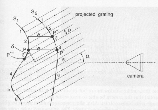
Projection moire is very similar, but involves making a slide of the master grating, and using (generally) a standard slide projector to cast fringes onto the test surface (cf. Diagram 2 below). A picture is taken from a normal view of the object and then the object is deformed and another picture is taken on the same film (double exposure), or two separate pictures are taken for later image combination. The difference between the pictures gives the change w in z-distance, using the equation
w = Np/(sin a).
Notice that this measurement does not give the contours of the specimen surface, but only a map of the w-differences between the two images. If a contour map of the specimen is wanted, a flat surface is placed in front of the specimen normal to the viewer, and the first picture is taken of the uniform grid lines on it. It should be pointed out that the moire fringes are never seen during data acquisition since the two images involved are observed separately, while the combination image can only be obtained later after some processing.
A major experimental difference is that the camera optics have to be good enough to resolve the grid lines. This is a disadvantage, however it can sometimes be compensated for by the fact that the grid need not be as large as the object, but only be large enough to make a slide. Therefore, the technique can be used on large objects. Note that the additional geometrical factor in analyzing the data is sin a, compared to the tan a used in shadow moire. This is due to the orientation of the grid: in projection moire, the grid is perpendicular to the collimated light source, while in shadow moire the grid is perpendicular to the viewer. It is assumed that the viewing device (eye, film, CCD, etc.) is far enough away, so that the angular spread of the image as seen by the viewer is very small. If this condition is not met, geometric compensation factors must be used. An appropriate equation that is claimed to give 1% accuracy will be found in the class text on page 188. The formula is so complex that it is feasible only when the image analysis is done by computer. Again, it must be remembered that there should be no lateral motion of the object.
Diagram 2. Layout for Projection Moire (from textbook) :

![]()
Visitors to this page :