![]()
1. In the standard imaging equation 1/f = 1/p + 1/q, under what circumstances will q be negative?
q is the image distance from the lens, and is considered positive if it is in image space, i.e., where you expect the light to form an image. For a lens, the image space is on the opposite side of the lens from the incoming light, while for a mirror the image space is on the same side of the mirror as the incoming light. When q is positive, you get a real image formed with real light. E.g., for a plane mirror, the usual image is behind the mirror and is virtual because there is no real light forming the image; while on the other hand, for a curved mirror, the real image, if one exists, is formed with real light converging in front of the mirror.
2. Starting with unpolarized light, how does one produce circularly polarized light?
First run the light through a standard linear polarizer such as a polaroid sheet. Then pass this linearly polarized beam through a quarter-wave plate with the plane of polarization at 45 degrees to the orthogonal axes of the quarter-wave plate. This will result in two equal magnitude components in quadrature, thus producing circularly polarized light.
3. What is meant by optical retardation and how is it related to birefringence?
Birefringence is a property of certain materials such that there are two indices of refraction for incoming light. The incoming light beam is broken into two components with orthogonal polarizations and travels at different speeds for each polarization component. This will introduce an optical path difference between the two components which depends on the amount of birefringence (n1 - n2) and the thickness s of the material. Retardation is the optical path difference Ds or the phase difference Df = kDs introduced between the two orthogonally polarized components of the light passing through the material and is measured as R = (n1 - n2)s.
4. What does it mean to optically remove a quarter-wave plate from a polariscope?
It is obvious what is meant by physically removing a quarter-wave plate (QWP), but it is not so clear what is meant by optical removal. To optically remove a QWP is to prevent it from creating components from the light going through it. This can be achieved by rotating the polarizer (and the analyzer to keep a dark-field system) until the axis of the polarizer is aligned with one of the axes (either fast or slow) of the QWP. In this way all of the linearly polarized light will travel down just one of the axes of the QWP and there will be no division of the incoming wave into two components. Thus the basic effect of the QWP is nullified.
5. What are the different camera requirements for shadow and projection moire?
In shadow moire, the master grid is placed right in front of the object surface and light is projected through the grid onto the surface. Viewing normally the interaction between the master grid and the shadow (specimen) grid produces a moire which contains information about the out-of-plane variations of the surface. To record this information, the viewing system need only record the (low frequency) moire, and does not need to resolve the (high frequency) grid lines.
On the other hand, in projection moire, a grid is projected on the object surface and two separate pictures are taken, either a before-and-after set (for strain), or first of a reference plane surface and then of the object surface (for contouring). The moire information is obtained later by suitably combining the two images. In this case, the viewing system must be able to resolve the actual grid lines in each of the two pictures. The moire effect is not seen until later when the grid-covered images are combined.
6. What are u-field and v-field maps? How would you use them to get gxy ?
A u-field map is a map of the fringes obtained from a system that is sensitive to motion in the x-direction (i.e., the grid lines are vertical), while a v-field map is a map of the fringes obtained from a system that is sensitive to motion in the y-direction (i.e., the grid lines are horizontal). To get gxy, add the cross-derivatives from each map, gxy = du/dy + dv/dx.
7. What procedural steps are followed to measure partial orders in photoelasticity using the Tardy method?
The first step is to determine the direction of the principal stresses (s1, s2). This requires isoclinic fringes, so the quarter-wave plates must be removed (no isoclinics are seen in a circular polariscope) either physically or optically. The polarizer/analyzer pair are rotated until an isoclinic is on top of the point of interest. The direction of the stresses is then the same as the rotation angle of the polarizer and analyzer. The next step is to determine the magnitude of the principal stresses by interpolating the fringe orders bracketing the point of interest since the magnitude of the stresses depends on the fringe order (s1 - s2) = CN/t where C is the stress-optic coefficient for the particular material, N is the fringe order, and t is the material thickness (material is assumed to be a plane slab). To do this, replace the QWPs to remove the isoclinics, and then , leaving the polarizer where it is, rotate the analyzer alone, changing the polariscope configuration from a dark-field setup to a bright-field setup. This will cause linearly polarized light that was previously blocked by the polarizer to pass through, and light that was originally passed by the polarizer to be blocked. The effect of this is to shift the fringes by half a fringe order. Thus a rotation of the analyzer through 90 degrees will change fringe locations by half a fringe count. Now, for some arbitrary rotation a (less than 90 degrees) that moves a bounding fringe right over the point of interest, the relationship which determines the partial fringe order of the point of interest is given by a/180. If the higher order fringe moves down over the selected point, subtract the fractional fringe value from the higher count, while if the lower order fringe moves up over the selected point, add the fractional fringe value to the lower value.
8. What is the physical meaning of an isoclinic line in a photoelastic pattern? How can isoclinics be removed?
An isoclinic line gives the locus of all points in a stress field where the direction of a principal stress is aligned with the axis of the input linear polarizer in a dark-field polariscope. All the linear polarized light will follow this stress axis, there will be no birefringent effect, and the light coming out of the sample will be extinguished by the crossed analyzer. This cancellation is independent of wavelength. Note that the quarter wave plates must be removed to obtain isoclinics because otherwise the light going through the sample will be circularly polarized and there will be a birefringent effect. If the QWPs are left in, no isoclinics will be observed.
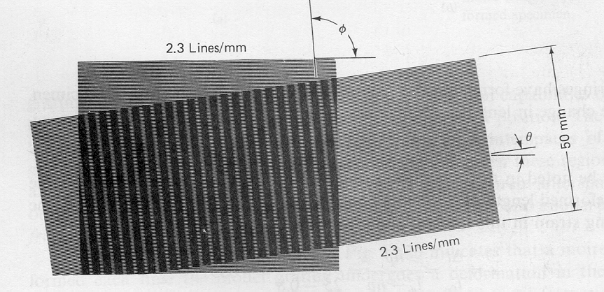
9. In the moire shown below in Figure 1, determine the amount of rotation undergone by the sample. (Actually, since you can see the full intersection of the grids, you can directly measure the angle. However, assume that you can only see the central region with the moire and that you know the master grid is 50 mm wide, has a grid density of 2.3 lines/mm, and is aligned with its lines horizontal.. You may also assume there is no strain.)
If there is only simple rotation, the moire can be analyzed for the rotation by f = p/2 + q/2. If there is only simple strain (without rotation) can be interpreted by u = Np, together with exx = du/dx. However, if there is a combination of rotation and strain, two linked equations must be used: tan q = (sin f)/(d/p + cos f) and p' = pd/(p =/- d), with e = (p' - p)/p, where p is the given pitch of the master grating and d is the moire spacing. All angles (f and q) are measured with respect to the direction of the master grid lines.
Thus to determine rotation angle q in Figure 1, just measure f from the figure and solve for q = 2f - p. However, if you disregard instructions and actually measure q from the figure, you will find your answer for q from the equation does not agree with the measured value. This is because when the image was copied onto the exam sheet it was resized, and I did not keep the original aspect ratio. This effectively introduced a uniform strain. If you solve the problem using the linked equations given above, you will get the value for q which agrees with the measured value. Since you were told there was no strain and just to solve for rotation, the first method applied only to the moire area gives the asked for (not however actual) answer. I accepted either approach, since the difference between uniform strain and rotation cannot be detected solely by looking at the moire area, and I told you there was no strain.
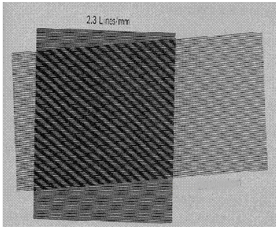
10. What is the strain and rotation indicated by the moire shown below in Figure 2? The master grid is 50 mm wide, has a line density of 2.3 lines/mm, and is aligned with its lines horizontal.
Here, it is specifically stated that you should expect a strain, so use the given p and the specified direction, measure d and f from the moire, and then solve the two linked equations for q and p'. Finally, get e by using e = (p' - p)/p.
![]()
Figure 1. Rotated grids with no strain.

![]()
Figure 2. Moire from rotation and uniform strain.

![]()
Last Modified on April 20, 1997